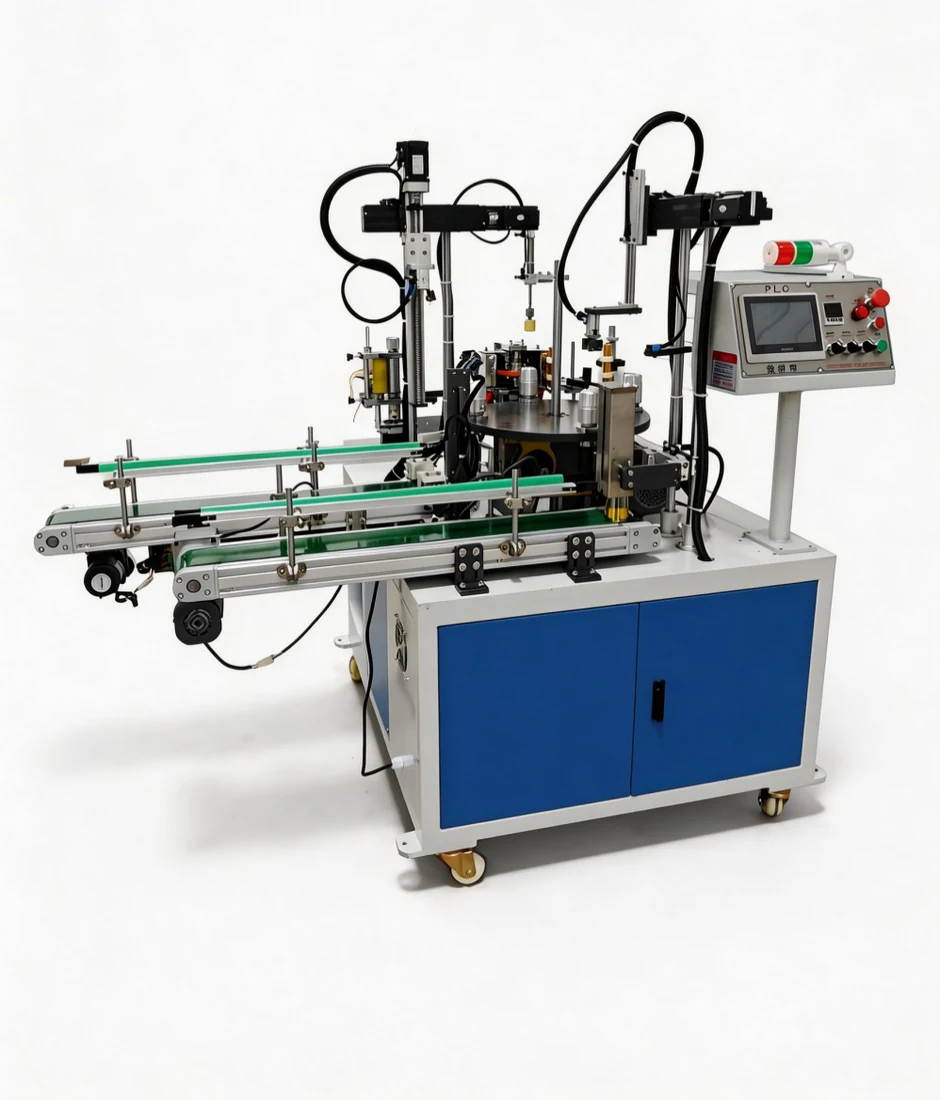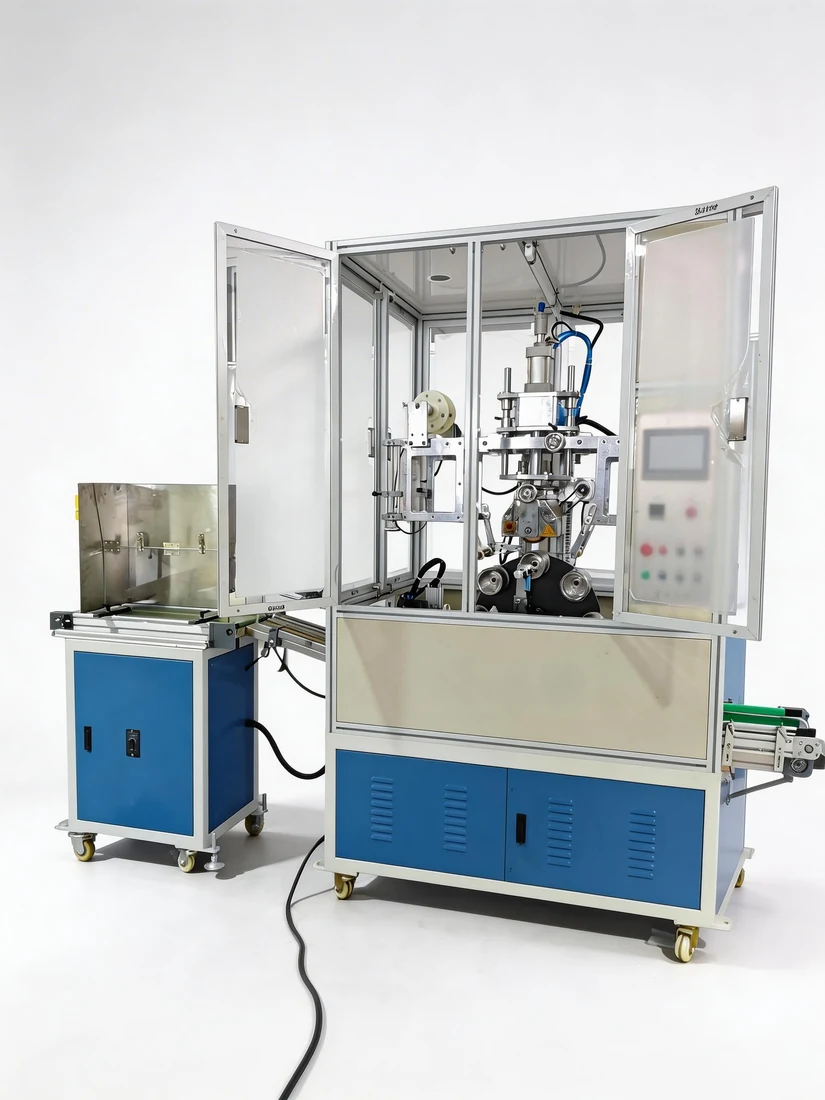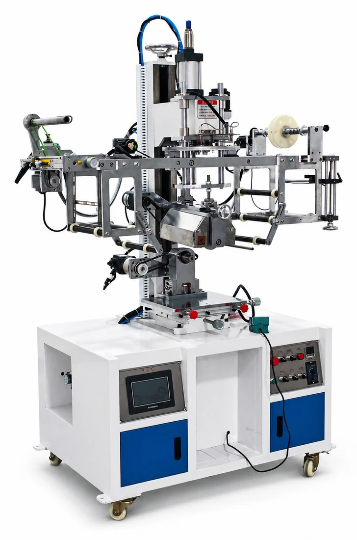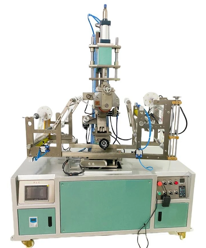
Application

Decoration Machines for Cups, Buckets, and Containers

Solutions for tapered cups, paint buckets, chemical pails, flower pots, sauce buckets, and round or tapered container decoration.

Product requirements

What determines the machine choice

  1. 01

    Large-end and small-end diameter

  2. 02

    Container height and printable height

  3. 03

    Handle, ribs and local interference

Production setup

Choose the production setup

  1. 01

    Cylindrical circumference transfer

  2. 02

    Tapered fixture and developed artwork

  3. 03

    Automatic feeding with orientation

Application evidence

Machines and finished products

Decision framework

Classify the requirement before changing the process

This route covers cylindrical and tapered containers, but those shapes must not be treated as one setup. Selection begins with wall geometry, supported print height, decoration coverage and the way each part is loaded and located.

01

Classify the side wall

Record the upper and lower diameters at the print band. Equal diameters describe a cylindrical route; different diameters require tapered-fixture and artwork-development checks.

02

Define the supported print band

Product height is not the same as printable height. Rims, handles, ribs, draft changes and soft wall sections may interrupt support or the roller path.

03

Choose panel or circumference decoration

A local panel needs a repeatable start datum. A full or near-full wrap also needs seam geometry, artwork pitch and circumferential motion to agree.

04

Set the loading and output route

Large pails, light cups and containers with handles require different feeding and orientation methods. Automation is chosen after proving that the part can be presented to the fixture consistently.

Field diagnosis

A check sequence from symptom to proof

Observed symptomPriority judgementCheck firstHow to confirm
Seam opens at one end or forms an hourglassTaper, artwork development, fixture angle or contact-path mismatchCompare the seam at the top, centre and bottom; confirm both diameters and the supported print height.Make one geometry correction only and use the direction of seam change to choose the next step.
A band repeats light or dark each revolutionPart roundness, fixture concentricity, wall support or periodic speed variationMark the angular position of the defect and see whether it follows the part, fixture or machine.Reload or rotate the part datum and repeat without changing process energy.
Artwork length or seam position driftsSurface-speed mismatch, slip, changing film tension or unstable product locationSeparate a constant offset from an error that accumulates over consecutive parts.Observe the same datum for several cycles and identify which motion changes first.
Wrinkle begins near one film edgeRoller-axis alignment, unequal edge tension or an angled entry pathTrace both film edges before, through and after the contact zone.Correct geometry before changing heat; the wrinkle origin should disappear during dry motion.

Release criteria

What a stable result looks like

  • The upper, centre and lower portions of the decoration meet the agreed seam and position standard.
  • The container remains round and undamaged, with no unacceptable rim, handle or rib interference.
  • Film tracking, peel and rewinding remain stable through consecutive cycles.
  • The approved result repeats after normal reloading, not only on one carefully positioned sample.

Connected evidence

Continue with the related machine, route and method

These routes are connected by selection conditions, process mechanism and validation order; they do not imply universal machine fit.

Contact Hengfa

Tell us about your product

Send product photos, dimensions, material, artwork position and output target. We will recommend a suitable machine configuration.

International contactljw1140551274ljw@gmail.com

Email